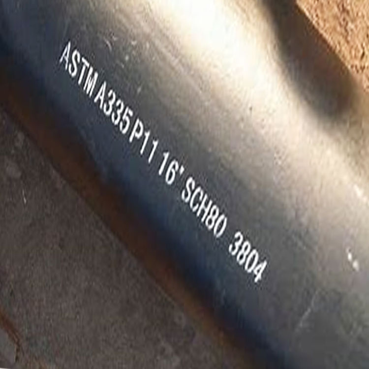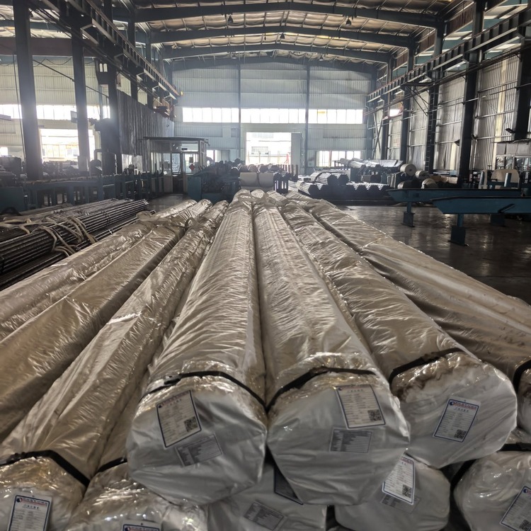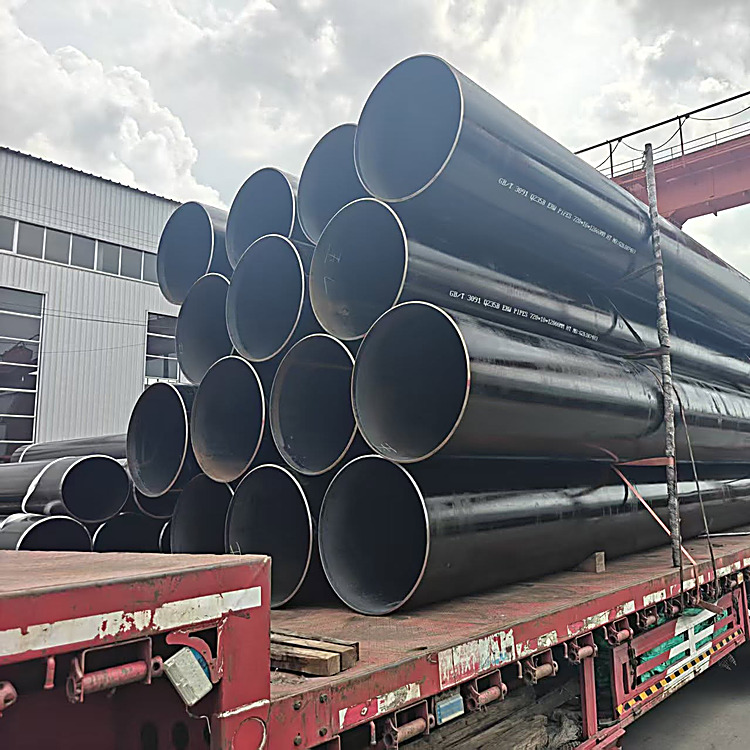
X80 LSAW pipe for gas transmission is rolled on JCOE lines from 406 mm to 1422 mm outside diameter with wall to 50.8 mm, and on UOE lines from 508 mm to 1220 mm up to 40 mm wall, in lengths of 12 a...
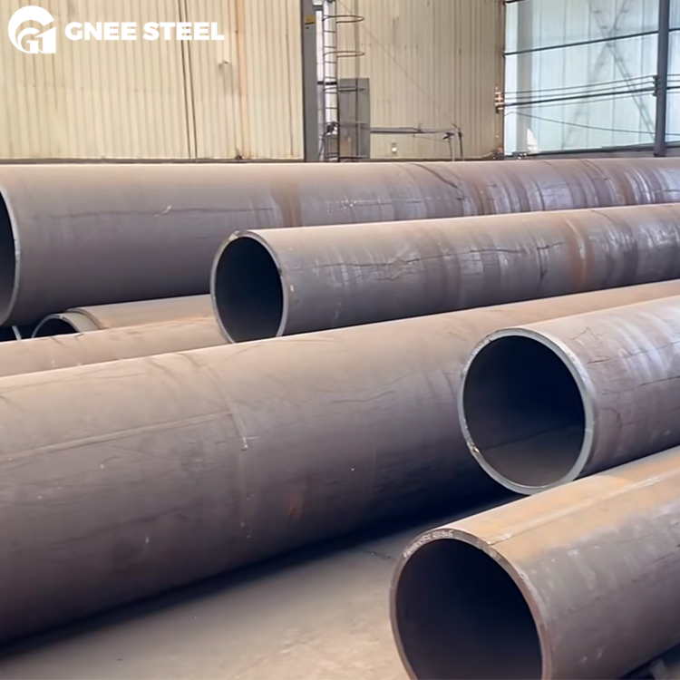
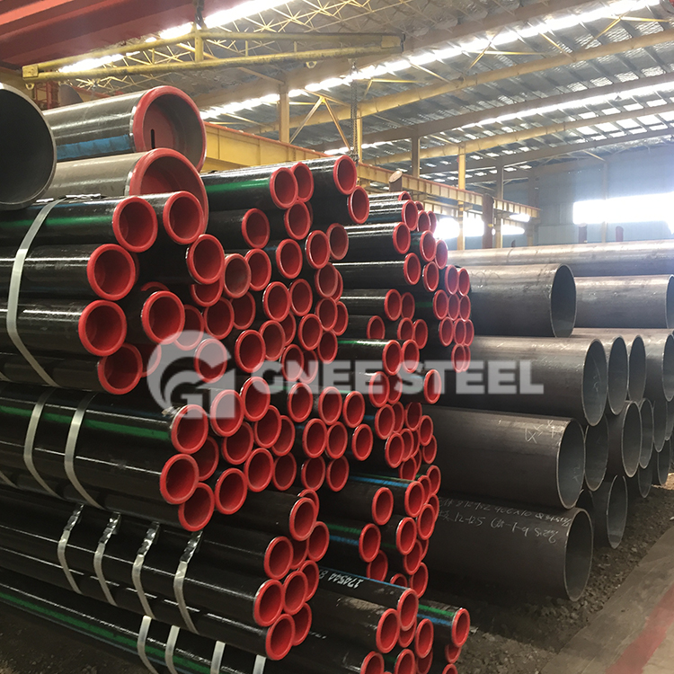
X80 LSAW pipe for gas transmission is rolled on JCOE lines from 406 mm to 1422 mm outside diameter with wall to 50.8 mm, and on UOE lines from 508 mm to 1220 mm up to 40 mm wall, in lengths of 12 and 18 m with 24 m available on UOE. Heavier wall and larger diameter go to rolled-and-welded construction, single or double seam, up to 2000 mm and 80 mm. Pipe is supplied as X80M (thermomechanically rolled) or X80Q (quenched and tempered). Each joint is hydrostatically tested, the longitudinal seam is scanned over its full length by ultrasonic or phased array, and PSL2 testing covers Charpy from body, seam and heat-affected zone plus drop weight tear tests where the specification calls for them. Three-layer polyethylene, three-layer polypropylene and fusion bonded epoxy coatings are applied before shipment, and every bundle ships with an EN 10204 3.1 certificate, with 3.2 available when a third-party inspector is required.
| Item | Specification |
|---|---|
| Standard | API 5L (46th edition) / ISO 3183 |
| Grade | X80 / L555 |
| Product specification level | PSL2 only — no PSL1 X80 exists |
| Delivery condition | X80M (thermomechanical rolled), X80Q (quenched and tempered) |
| Product form | LSAW / SAWL, single longitudinal seam; SSAW where the design permits |
| Forming routes | JCOE, UOE, rolled and welded (single or double seam) |
| Outside diameter | 406–1422 mm (16–56 in) JCOE; 508–1220 mm UOE; to 2000 mm double seam |
| Wall thickness | 8–50.8 mm on JCOE/UOE; to 80 mm on rolled heavy wall |
| Length | 12 m, 18 m; 24 m on UOE |
| Yield strength | 555–705 MPa (80,500–102,300 psi) |
| Tensile strength | 625–825 MPa (90,600–119,700 psi) |
| Yield to tensile ratio, OD > 323.9 mm | ≤ 0.93 |
| Weld tensile, min | 625 MPa (90,600 psi) |
| Chemistry, X80M | C 0.12 max, Mn 1.85 max, P 0.025, S 0.015, CEIIW 0.43, CEPcm 0.25 |
| Chemistry, X80Q | C 0.18 max, Mn 1.90 max, P 0.025, S 0.015, CE as agreed |
| Boron | 0.004% max |
| Pipe ends | Bevelled 30° with 1.6 mm root face, or as specified |
| Coating | 3LPE, 3LPP, FBE; internal flow coating on request |
| Testing | Hydrostatic, 100% seam UT or PAUT, CVN body/seam/HAZ, DWTT where specified, hardness, dimensional |
| Documentation | EN 10204 3.1 or 3.2 MTC, API 5L monogram on request |
X80 is not made by adding alloy until the strength arrives. It is made by keeping carbon low and controlling the rolling schedule, so that a fine ferrite-bainite microstructure delivers 555 MPa with good toughness. Carbon at 0.12% for the M grade is the key number: it keeps the heat-affected zone soft enough to weld without hydrogen cracking, and it pushes the carbon equivalent assessment onto CEPcm, which is the more relevant measure at low carbon.
| Element, max % | X80M | X80Q |
|---|---|---|
| C | 0.12 | 0.18 |
| Si | 0.45 | 0.45 |
| Mn | 1.85 | 1.90 |
| P | 0.025 | 0.025 |
| S | 0.015 | 0.015 |
| Nb + V + Ti | 0.15 | 0.15 |
| Cu / Ni / Cr / Mo | 0.50 / 1.00 / 0.50 / 0.50 | 0.50 / 1.00 / 0.50 / 0.50 |
| B | 0.004 | 0.004 |
| CEIIW | 0.43 | As agreed |
| CEPcm | 0.25 | As agreed |
Limits from API 5L Table 6. Alloy limits are the standard values unless otherwise agreed in the purchase order.
Two things in that table cause problems on real orders. First, X80Q has no tabulated carbon equivalent. The standard leaves it “as agreed”, which means the buyer must either accept whatever the mill produces or write a project limit into the order. Discovering the actual CEPcm on the mill certificate, after the welding procedure has been qualified, is a common and entirely avoidable delay.
Second, the 0.12% carbon threshold is not a formality. The carbon equivalent rule switches from CEIIW to CEPcm at exactly that carbon level, so an M grade sits on the boundary and both numbers have to be read together. A heat at 0.11% carbon is assessed on CEPcm ≤ 0.25; a heat at 0.13% is assessed on CEIIW ≤ 0.43. Same grade, different rule.
| Property | X80M / X80Q |
|---|---|
| Yield strength, min | 555 MPa (80,500 psi) |
| Yield strength, max | 705 MPa (102,300 psi) |
| Tensile strength, min | 625 MPa (90,600 psi) |
| Tensile strength, max | 825 MPa (119,700 psi) |
| Yield to tensile ratio, OD > 323.9 mm | 0.93 max |
| Weld seam tensile, min | 625 MPa |
| Elongation | Calculated from the API 5L formula |
The maximum is as important as the minimum, and buyers coming from lower grades often miss it. A heat at 730 MPa yield on an X80 order is a rejection, not a bonus. Over-strength pipe raises the hoop stress at the design pressure, pushes the yield-to-tensile ratio toward the 0.93 ceiling, and reduces the plastic reserve the fracture control calculation assumes.
Elongation is calculated rather than fixed. The API 5L formula returns a minimum that depends on the cross-sectional area of the test piece and the specified tensile strength, so quoting a single figure across every size is wrong. Ask for the calculated value against the actual diameter and wall.
| OD | Typical gas line wall | D/t at that wall | Route |
|---|---|---|---|
| 762 mm (30 in) | 12.7–19.1 mm | 40–60 | JCOE |
| 914 mm (36 in) | 14.3–22.2 mm | 41–64 | JCOE |
| 1016 mm (40 in) | 15.9–25.4 mm | 40–64 | JCOE |
| 1219 mm (48 in) | 18.3–28.6 mm | 43–67 | UOE / JCOE |
| 1422 mm (56 in) | 21.4–33.0 mm | 43–66 | JCOE / rolled |
Walls shown cover the practical range for high-pressure gas at design factors of 0.72 and below. The governing wall for a specific line comes from the design calculation.
| Parameter | Typical LSAW tolerance |
|---|---|
| Outside diameter | ±0.5% of OD, or ±3.2 mm, whichever is smaller |
| Wall thickness | API 5L Table 10 governs; −0 / +15% is a common shop capability |
| Length | +50 / −0 mm on fixed lengths |
| Straightness | ≤ 0.2% of length |
| Ovality, expanded pipe | ≤ 0.5% of OD on JCOE; ≤ 0.3% on a well-set UOE line |
| End squareness | ≤ 1.6 mm on bevelled ends |
The coating cutback at each end is left bare, typically 100 to 150 mm, so the girth weld can be made and then protected with a heat-shrink sleeve. On X80 it is worth confirming that the coating application temperature stays inside the range that preserves the pipe’s toughness, since an overheated coating cycle can undo what the rolling schedule achieved.
Send the line schedule with diameter, wall, grade and delivery condition, total length, design pressure and class location, and the toughness and DWTT requirements your design calculation produced. We will come back with a priced offer that names the test package, the certificate type and the coating system on the same document, so nothing is left to interpretation between the offer and the mill order.
No. API 5L PSL1 covers grades up to X70. X80 is a PSL2 grade only, so every X80 order carries mandatory Charpy testing, a bounded strength window, carbon equivalent limits and full traceability whether or not the buyer asked for them.
X80M for the great majority of onshore main line work. Thermomechanical rolling gives a fine grain structure with good toughness at a lower carbon level, which is friendlier to field welding, and it is the condition most mills supply from stock plate. X80Q is chosen where the specification needs a tighter strength window or toughness at low temperature; it carries a full heat treatment cycle and an agreed carbon equivalent rather than a tabulated one, so it costs more and takes longer.
About 12.5%, because the minimum yield ratio is 485 to 555 MPa. On a 1219 mm line at 12 MPa that is 18.3 mm of wall against 20.9 mm, or 542 kg/m against 619 kg/m. Against X52 the saving is around 35%, but few high-pressure gas lines are designed at X52 today, so the real comparison is usually X70 against X80.
Because compressed gas stores energy that drives a running fracture. If a gas line ruptures, the decompression wave and the fracture tip travel at comparable speeds, and whether the crack arrests depends on the steel’s resistance to propagating fracture. DWTT measures that resistance on a full-thickness specimen. A liquid line decompresses almost instantly and the driving force disappears, so the requirement usually does not apply.
In principle, under API 5L Annex H, and in practice rarely. Meeting the hardness ceiling and passing HIC and SSC testing at 555 MPa minimum yield is difficult and expensive, and the number of mills with qualified experience is small. Most projects route the sour section in X65 or a dedicated sour grade and keep X80 for the sweet part of the line.
1422 mm (56 in) on a JCOE line with wall to 50.8 mm, and 1220 mm on UOE with wall to 40 mm but lengths to 24 m. Beyond that, rolled-and-welded construction reaches 1600 mm with a single seam and 2000 mm with a double seam, at walls up to 80 mm.
Not necessarily, and often they are not. X80 elbows, tees and reducers come from a small number of mills with long lead times. Buying the line in X80 and the fittings in X70 or X65 with transition spools is accepted practice, provided the transition weld procedure is qualified and the design pressure at that location is checked against the lower grade.