Sch80 is a designation within the American standard system used to indicate a pipe’s wall thickness class. This designation is derived from the abbreviation of the English word “Schedule,” and a higher number corresponds to a thicker wall. Sch80 represents a moderately thick wall class, primarily utilized in operating environments involving high pressures or corrosive media.
The following table is based on the ASME/ANSI B36.10M standard (covering NPS 1/8″ to 24″).
| NPS (Nominal Pipe Size) | DN (Diameter Nominal) | OD (Outside Diameter) [Inches] | OD (Outside Diameter) [mm] | SCH80 Wall Thickness (WT) [mm] | ID (Inside Diameter) [mm] | Theoretical Weight [ kg/m ] |
| 1/8″ | DN 6 | 0.405 | 10.3 | 2.41 | 5.48 | 0.47 |
| 1/4″ | DN 8 | 0.540 | 13.7 | 3.02 | 7.66 | 0.80 |
| 3/8″ | DN 10 | 0.675 | 17.1 | 3.20 | 10.70 | 1.10 |
| 1/2″ | DN 15 | 0.840 | 21.3 | 3.73 | 13.84 | 1.62 |
| 3/4″ | DN 20 | 1.050 | 26.7 | 3.91 | 18.88 | 2.20 |
| 1″ | DN 25 | 1.315 | 33.4 | 4.55 | 24.30 | 3.24 |
| 1-1/4″ | DN 32 | 1.660 | 42.2 | 4.85 | 32.50 | 4.47 |
| 1-1/2″ | DN 40 | 1.900 | 48.3 | 5.08 | 38.14 | 5.41 |
| 2″ | DN 50 | 2.375 | 60.3 | 5.54 | 49.22 | 7.48 |
| 2-1/2″ | DN 65 | 2.875 | 73.0 | 7.01 | 58.98 | 11.41 |
| 3″ | DN 80 | 3.500 | 88.9 | 7.62 | 73.66 | 15.27 |
| 3-1/2″ | DN 90 | 4.000 | 101.6 | 8.08 | 85.44 | 18.63 |
| 4″ | DN 100 | 4.500 | 114.3 | 8.56 | 97.18 | 22.32 |
| 5″ | DN 125 | 5.563 | 141.3 | 9.53 | 122.24 | 30.97 |
| 6″ | DN 150 | 6.625 | 168.3 | 10.97 | 146.36 | 42.56 |
| 8″ | DN 200 | 8.625 | 219.1 | 12.70 | 193.70 | 64.64 |
| 10″ | DN 250 | 10.750 | 273.1 | 15.09 | 242.92 | 95.97 |
| 12″ | DN 300 | 12.750 | 323.9 | 17.48 | 288.94 | 132.04 |
| 14″ | DN 350 | 14.000 | 355.6 | 19.05 | 317.50 | 158.10 |
| 16″ | DN 400 | 16.000 | 406.4 | 21.44 | 363.52 | 203.53 |
| 18″ | DN 450 | 18.000 | 457.2 | 23.83 | 409.54 | 254.67 |
| 20″ | DN 500 | 20.000 | 508.0 | 26.19 | 455.62 | 311.18 |
| 24″ | DN 600 | 24.000 | 610.0 | 30.96 | 548.08 | 442.08 |
The calculation formula for Sch80 wall thickness is based on three core parameters: the pipe’s design pressure, the material’s allowable stress, and the corrosion allowance. The formula is expressed as follows:
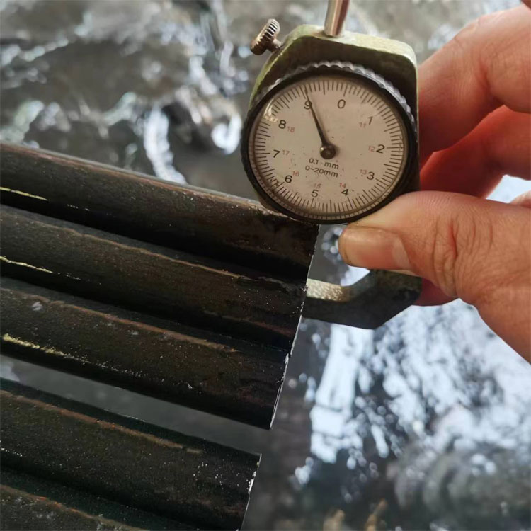
Wall Thickness = (Design Pressure × Outer Diameter) / (2 × Material Allowable Stress × Weld Joint Efficiency) + Corrosion Allowance. In practical application, variations in material strength must be taken into account; consequently, the calculated values for carbon steel pipes and stainless steel pipes will differ significantly. Furthermore, manufacturing tolerances must be considered during production, with the standard allowable deviation typically falling within ±12.5% of the nominal wall thickness.